
Game Board Kit 51
Recently I have been toying with the idea of learning to solder. There are many reasons why, but the main one is that whenever my electronics break and it is a simple part replacement I hate the idea of wasting sometimes hundreds of pounds to get them fixed.
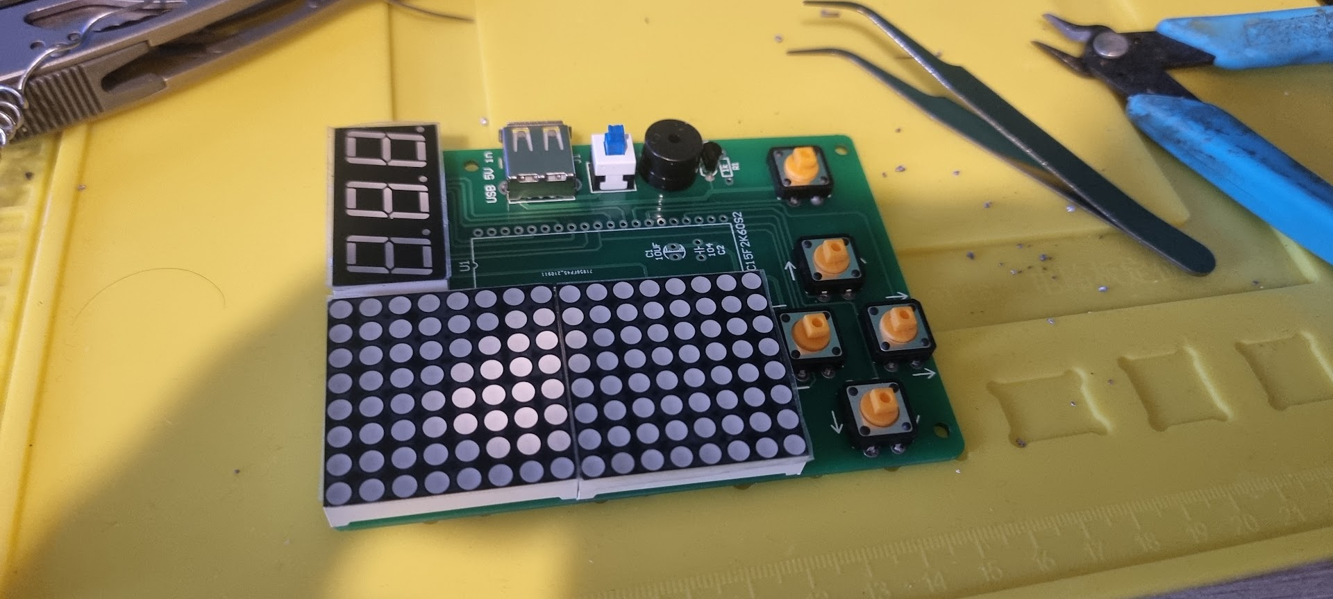
Enter the DIY Game Board Kit 51 from AliExpress. This £4.50 board was just cheap enough that I was not worried about destroying it in my first attempt at learning to solder the components on.

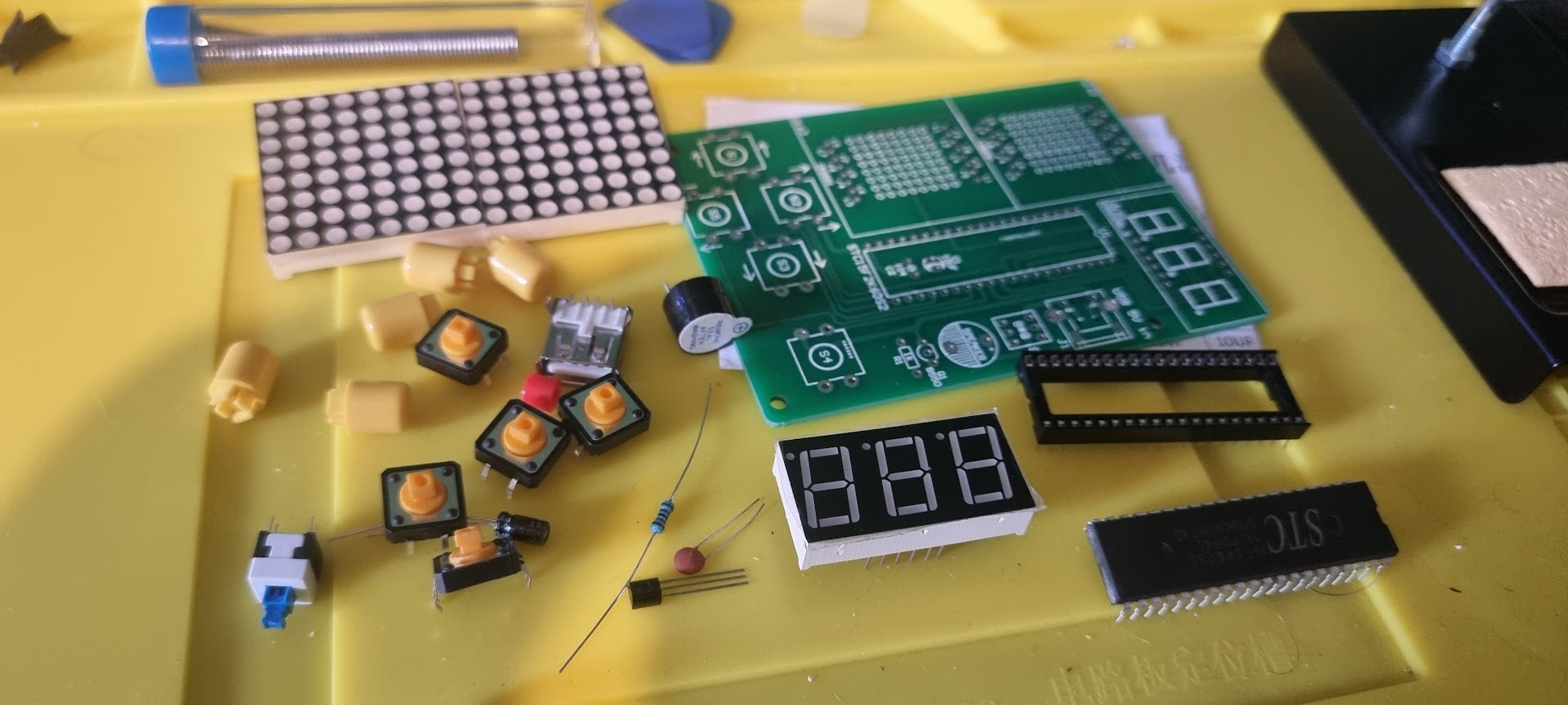
The part only took just over a week to arrive from AliExpress and I could not wait to get stuck in. I pulled up good old youtube and watched a few videos on learning the basics of soldering.
Now the next part of the blog follows my process of trying to build out this kit. You can see how impatient I am and what this meant as I went along. I will mark out stage and its issues with titles 'Hoops'.
Hoop 1
Upon opening up the kit's instructions it was then that I realized it was all written in Chinese. I did after all buy the kit from AliExpress. :(
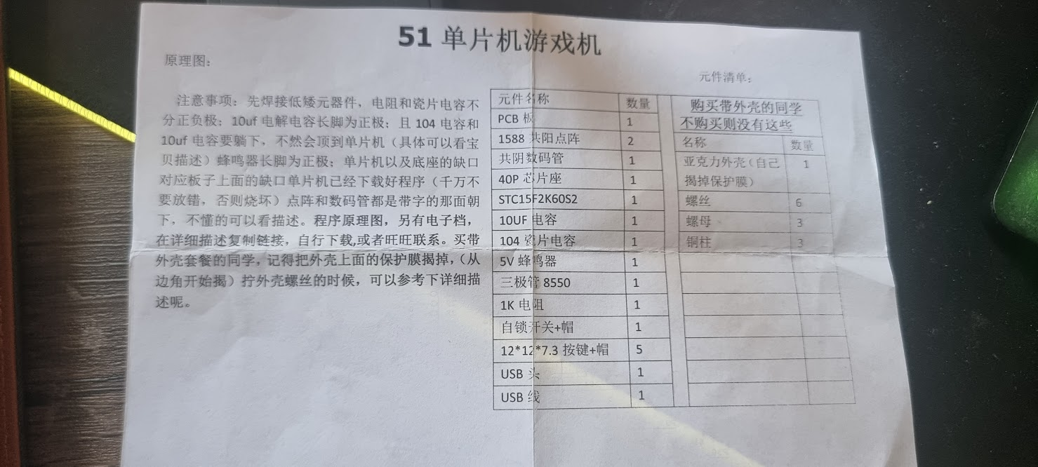
But fear not reader for we live in the future and with a little help from image translations, we manage to get the following instructions. Which I have also provided in text form below this image incase you stumble on this blog while also looking for help.
Precautions: First weld low-power components, resistors and ceramic capacitors are not
Divided into positive and negative electrodes: the long foot of the 10uf electrolytic capacitor is the positive electrode; and the sum of the 104 capacitors.
The 10uf capacitor must be deceived, otherwise it will hit the microcontroller (see treasure for details).
(Description) The long foot of the buzzer is positive; the gap between the MCU and the base
The microcomputer corresponding to the gap on the board has already downloaded the program (don't
Be misplaced, otherwise it will burn out) The dot matrix and the digital tube are both facing the side with the word
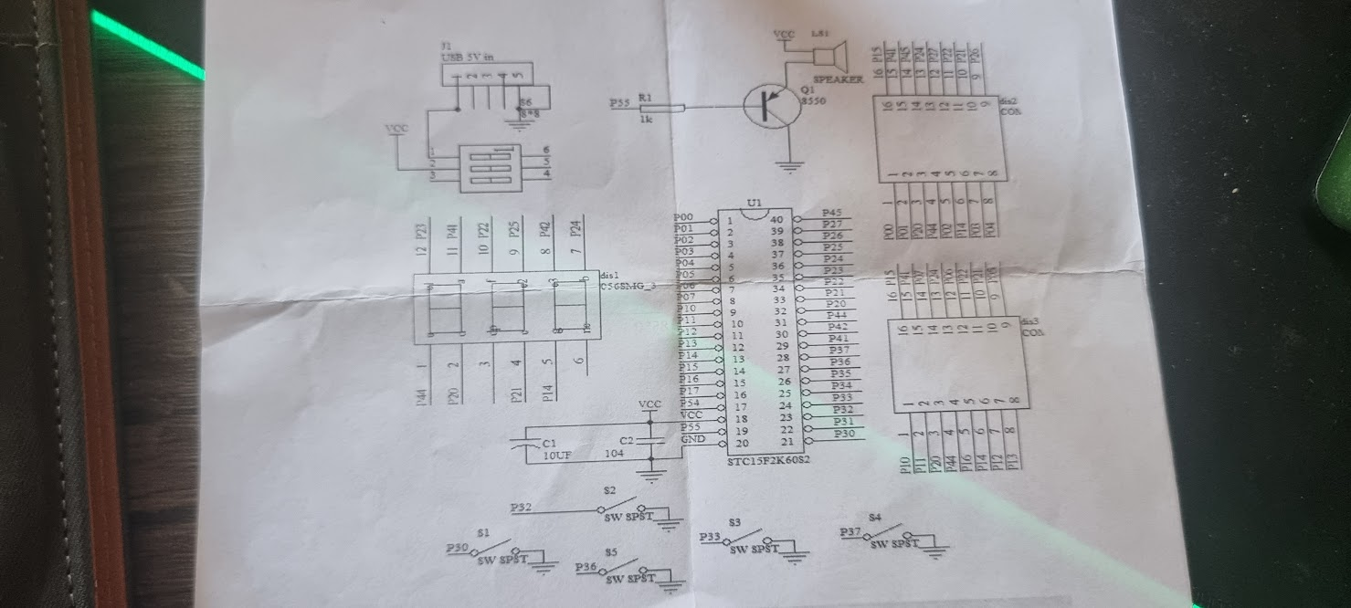
Next, if you don't understand, you can read the description. Program schematic diagram, there is also an electronic file,
Copy the link in the detailed description, download it yourself, or contact Wangwang. Buy belt
Students with shell packages, remember to remove the protective film on the shell, (from
The corners start to be exposed) When screwing the shell screws, you can refer to the detailed description below
Describe it.
So with my new instructions in place, I set off with my instructions on a quest to solder and be a game kit-making machine.
Hoop 2
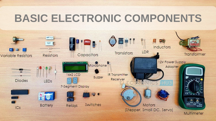
All was going well until I also realized that in my haste to just jump straight in and get soldering. I had also forgot that the basics electronics course I did when in college was over 15 years ago. I no longer had an idea what a resistor or a capacitor is and as such would not be able to understand which one needs to go where on the board. So another google later and this lovely diagram came to my rescue.
Hoop 3
Soldering continued, all the pieces were getting added to the board successfully, and felt that I was slowly getting better at soldering. That was until I plugged it in for the first time and tried to play with it.
The second matrix row of LEDs was turning on but some of the LEDs were permenantly online and some flashed. (I forgot to take a picture) . After some checking of the soldering joints and making sure nothing was touching one another I noticed during a re-reading of the instructions the following line.
' The dot matrix and the digital tube are both facing the side with the word STC15F2K6052'
In translated English this meant. That when installing the Dot Matrix of LED lights make sure the side with the text 'STC15F2K6052' is located facing the bottom of the device. I had not done this for the second set of LEDs.
Hoop 4
Damn. This takes me to the next hoop to solve. I now need to learn to de-solder. So back to youtube, I go and I was starting to feel like a yoyo opening up the browser over and over again. The video below gives a good look into different methods of de-soldering and I opted for the suction method.
Once I managed to get the led matrix off and then soldered back on again, I plugged in the device one more time and........
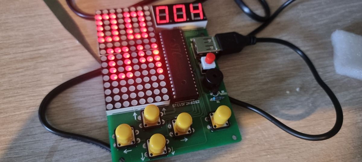
YERRRR..... SUCCESS.....
Here is a video of me playing a few lines of Tetris using the device. I feel like a kid all over again. There is nothing like that feeling of learning something new and having it come to fruition in a tangible way. I have now ordered a box for this to be stored in so I am not holding the board directly when trying to play with it.
So what's next...
Well. Who knows. I am now a soldering god, which means the world is my oyster and I can create unlimited power from the sun if I choose to.
All jokes aside, one project I have always wanted to do is upgrade my Gameboy advance to have an IPS LCD screen. So subscribe to this blog and get notified when I get around to doing that and while you are here follow me on Instagram for more images and videos of my journey into the electronics world.

